BEP PUSH BUTTON SWITCH - 24V LATCHING ON/OFF & MOMENTARY ON/OFF
BEP PUSH BUTTON SWITCH - 24V LATCHING ON/OFF & MOMENTARY ON/OFF
SKU:80-911-0062-00
Push Button Switch - 24V 80-911-0060-00 & 80-911-0061-00
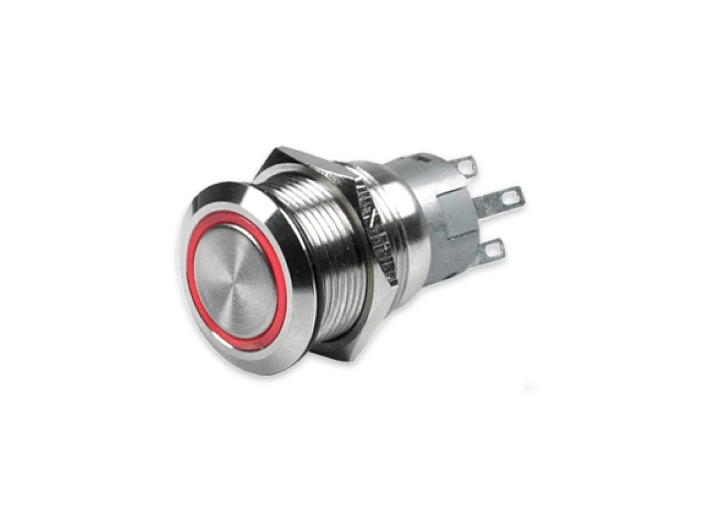
Push-button Switches are built to last with their stainless steel components and silver alloy contacts. The through panel mount switches are ideal for lighting, switch, or dash panels, with colored rings that can be wired to either display power to the system or switch back lighting. The product line includes both switches and warning buzzers with LED light rings.
Features:
- Maximum switch current rating 5 Amps
- IP67 environmental protection switches
Specifications
Specifications
Color: Blue or Red
Action: ON-OFF momentary or ON-OFF latching
Box Dimensions: 1"H x 1"W x 2"L WT: 0.05 lbs
UPC: 843687005513
Installation Details
Installation Details
Installing the BEP Marine 80-511-0003-00 switch involves preparing a 19mm panel cutout and wiring the five blade terminals. Because it is a marine-grade switch with an IP67 rating, proper sealing during mounting is essential.
1. Mounting Instructions
Panel Preparation: Drill a 19mm (3/4") hole in your dashboard or control panel.
Sealing: Place the included black O-ring over the switch body so it sits against the front flange.
Securing: Insert the switch into the hole and tighten the locking nut from behind. Ensure the O-ring is slightly compressed to create a watertight seal.
YouTube
YouTube
2. Wiring Guide (5-Terminal Layout)
The switch has five terminals usually labeled on the back: C (Common), NO (Normally Open), NC (Normally Closed), and two LED (+/-) pins.
A. Standard "On when Pressed" Setup
This is the most common configuration where both the device and the blue LED ring turn on when the button is pushed in.
Power In: Connect your fused 12V DC positive supply to the C (Common) terminal.
Power Out (Load): Connect your device's positive wire to the NO (Normally Open) terminal.
LED Positive: Create a small "jumper" wire between the NO terminal and the (+) LED terminal. This ensures the blue ring only lights up when the switch is active.
Ground: Connect the (-) LED terminal to your common negative/ground bus bar.
B. Always-On Blue Backlight Setup
Use this if you want the blue ring to stay lit so you can find the switch in the dark.
LED Positive: Instead of jumping from NO, connect the (+) LED terminal directly to your 12V power source.
Everything else: Wire the power and ground as described in the standard setup.
Pelagic Power Tip
Pelagic Power Tip
Important Safety Tips
Amperage Limit: This switch is rated for a maximum of 5 Amps. If you are powering high-draw equipment (like pumps or large light bars), you must use it to trigger a relay instead of wiring the device directly.
Corrosion Protection: Use marine-grade heat shrink butt connectors or female spade terminals to prevent salt-air corrosion on the connections.
20 in stock
Couldn't load pickup availability