Inverter Bypass Surface Mount Box with Circuit Breaker Lockouts
Inverter Bypass Surface Mount Box with Circuit Breaker Lockouts
SKU:INVBYPASS-30A-2P
The inverter bypass box is designed to provide a simple and safe method for bypassing an inverter system to continue powering AC loads.
In a common application, if you have a fault or failure of your inverter, you can switch the bypass breakers and AC power will feed your loads from an on board generator or other AC power source. Safely bypassing the inverter all together.
Being circuit breaker based, this also provides circuit breaker protection for the input and output of the inverter.
- Available in 30A or 50A
- 120V Single Phase or 240V Split Phase options
- Suitable for Inverters 2000W to 5000W
- Custom insulated tin plated copper bus bars
- 1/2in studs for simple secure termination of
- Heavy duty sealed enclosure with gasketing
- Includes Cable Glands
Check out our wide selection of inverter chargers available here.
Under normal operation:
- AC loads are supplied through the inverter system (pass-through or inverted output depending on system state)
When bypass is engaged:
- AC input (shore or generator) is routed directly to the load side
- The inverter is electrically isolated from the circuit path
This allows for inverter removal or servicing without loss of AC functionality, eliminates unintended backfeed conditions, and provides a controlled system fallback in the event of inverter failure.
Electrical Architecture
- Dedicated input terminals for shore or generator feed
- Inverter input and output routing points
- Load-side distribution terminals
- Internal switching or relay-based transfer mechanism (model dependent)
All bus bars are custom made, tinned copper, dipped in insulation for corrosion resistance and safety. Termination points designed to support up to 6 AWG wire to support marine-grade installations with the correct size wire for the load.
Designed For The Real World
This product was developed from real world installations by installers and engineers who work in the field on a daily basis.
Add reliability and redundancy to your inverter system using the Inverter Bypass Box
Specifications
Specifications
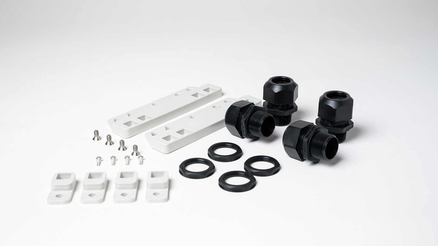
Parts Included:
Cable Grips (4)
Mounting Stainless Steel Screws (4)
Plastic Mounting Feet (4)
Screw Hole Fillers (4)
PolyGuard Enclosure
Bypass Panel
Bypass Panel Screws (4)
UL Listed PolyGuard Enclosure
Recommended Wire Sizes:
MODEL NUMBER/BREAKER AMPERAGE/MINIMUM WIRE SIZE
INVBYPASS-30A-2P 30 AMP BREAKER 10 AWG
INVBYPASS-50A-2P 50 AMP BREAKER 6 AWG
INVBYPASS-50A-2P. 50 AMP BREAKER 6 AWG
Recommended Inverter Pairing Chart:
SKU Voltage Inverter Watts
INVBYPASS-30A-2P 120V 2000W – 3000W
INVBYPASS-50A-2P 120V 3500W – 5000W
INVBYPASS-50A-2P 240V 3500W – 5000W
Installation Details
Installation Details
INSTILATION GUIDE
The bypass box should be installed in a dry, well-ventilated area that is protected from direct exposure to moisture, spray, and excessive heat. Ideal mounting locations include interior compartments near the inverter or AC distribution panel where environmental conditions remain stable.
Avoid installation in areas subject to washdown or standing water. Moisture and heat exposure can significantly reduce the lifespan of electrical components and increase the risk of corrosion or failure.
Cable glands come with each bypass box to support appropriate size triplex wire.
3/4in Gland for 30A
1in Gland for 50A
When installing drill appropriate size holes in the box to accept the glands in an orientation specific to your installation.
The bypass box is designed to be surface mounted with included mounting feet. It can also be rear panel mounted by removing the enclosure cover and mounting via the threaded nuts in the enclosure.
Before beginning any wiring, ensure all AC and DC power sources are fully de-energized. Confirm the absence of voltage using a properly rated multimeter.
Read user manual for complete installation details.
Pelagic Power Tip
Pelagic Power Tip
When installing a new or upgraded inverter using a bypass box provides the circuit protection required for your inverter while giving your system the ability to bypass in the event of an inverter failure.
There is an AC ground stud built in to the back of the back of the panel. We recomend you do your AC grounding outside the bypass box and simply run a common AC ground in to the panel for the stud.
Low stock: 5 left
Couldn't load pickup availability